Mica insulated strip heaters are economical heat sources, suitable for providing heat to flat surfaces. The sheath temperature is limited to 900°F. Maximum allowable watt densities with respect to application temperatures are shown in the diagram. However, for temperatures below 500°F, 20 Watts/in² is a safe value.
In order to secure efficient heat transfer and avoid thermal expansion issues that detach strip heaters from the surfaces that they are applied to, strip heaters can be made to include several mounting holes or pressure plates that provide rigidity and improve heat transfer uniformity.
Mica insulated strip heaters are available in many electrical termination styles, and within certain design limitations can accommodate holes and cut-outs.

| Max Sheath Temp | 900°F |
| Max Voltage | 600V |
| Max Amps | 25 Amps |
| Max Safe Watt Density | 20 w/in2 |
| Wattage Tolerance | +5%, -10% |
| Approx. Thickness | 3/16″ |
| Min. Width | 3/4″ |
| Length Tolerance Up to 18″ Over 18″ | +/- 1/16″ +/- 1/8″ |
| Width Tolerance | +/- 1/16″ |
| Top Sheet Bottom Sheet | Stainless Steel 430 Aluminized Steel |
Screws are the most commonly used terminals on strip heaters. They are recommended for high amperages (max 25 Amps). 10-32 screws are standard. Other sizes are available.


To avoid internal damages, screws should not be tightened excessively (30 in-lbs). It is good practice to use a backup wrench on the lower nut for counter-torque.

Terminal boxes eliminate the risk of electric shocks and shorts by enclosing the terminals in a heavy-duty stainless-steel box. These boxes come in two styles, G1 and G2. For three-phase and dual voltage applications, special boxes are used.
| W x L x H (in) | |
| G1 | 1 5/8″ x 2″ x 1 5/8″ |
| G2 | 2″ x 2 1/4″ x 1 3/4″ |

Ceramic terminal covers provide a cost-effective way to avoid electric shocks and shorts. These covers require 1″ long screws.
Internally connected high-temperature lead wires provide a safer electrical connection. However, it is physically impossible to conceal heavy gauge wire under the top metallic sheet. This limits the maximum amperage applicable to 20 Amps.


Single or double ended mica insulated high temperture wire with or without SS braids.

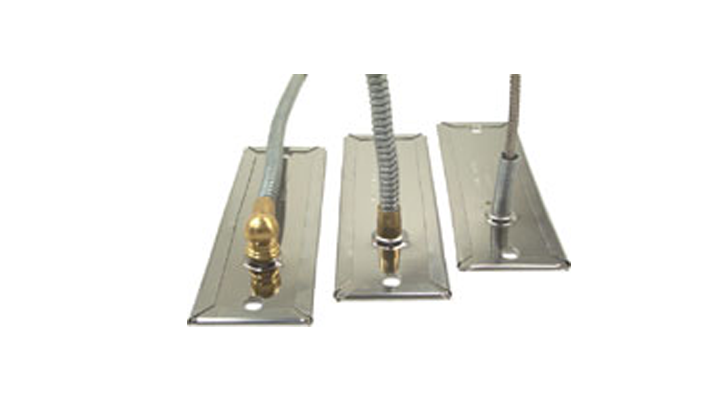
Straight armor cable provides excellent protection against abrasion and contamination. Sharp bending is not possible with this type of lead.

Armor cable with a 90° elbow (which can have any orientation) is for applications where height restrictions make straight armor cable exits unsuitable.

Stainless steel braids provide strength and protect leads from abrasion. Moreover, sharp bends are possible with this type of lead.
High-temperature European plugs eliminate all possible exposure to live connectors. They are ideal in applications where the electrical termination gets disconnected frequently.

Mounting slots, holes and cut-outs can be incorporated into the design of mica strip heaters. However, there design limitations considered and the should be consulted prior to placing any order.

Mica strip heaters are versatile and can be made into any irregular shape (within design limitations). They can also be multi-sided; “L” shaped, “U” shaped or rectangular. It should be noted that for efficient heat transfer, multi-sided strip heaters should be backed with pressure plates.

Aluminum Strip Heaters combine the rugged construction of tubular heaters and the high thermal conductivity of an aluminum housing structure that acts as a heat-sink and uniformly dissipates the heat absorbed from a set of 0.315” diameter tubular elements. Aluminum Strip Heaters can have different lengths but are only available in four standard widths; 1.5”, 2.5”, 3” and 4”. They can be made with different termination styles and can accommodate thermocouple holes (max 0.25”). In order to secure efficient heat transfer Aluminum Strip Heaters should be fastened to a surface using hold-down clamps or mounting screws. Due to construction limitations mounting holes can only be placed along the dotted lines shown in the diagrams below.
Mounting Slots (9/32” x 5/16”) and Thermocouple Holes (1/4”) can be made along the vertical centerlines or dotted lines within the allowed limits.

| Max. Temperature | 650°F |
| Max. Voltage | 300V |
| Max Amps | 25 Amps |
| Max Safe Watt Density | 20 w/in2 |
| Wattage Tolerance | +5%, -10% |
| Resistance Tolerance | +10%, -5% |
| Approximate Thickness | 1/2″ |
| Cover Plate | SS 430 |
| B1Style The standard termination style on Aluminum Strip Heaters. Tubular ends folded at a right angle with terminal lugs and 10-32 binder-head screws. |  |
| B2 Style Tubular ends exiting straight from the edge of the strip heater with 10-32 stud terminals. |  |
| H Style Encasing cables in metallic flexible tubing is the ideal method to protect leads from abrasion and contamination. Sharp bending is not possible with this type of leads. | 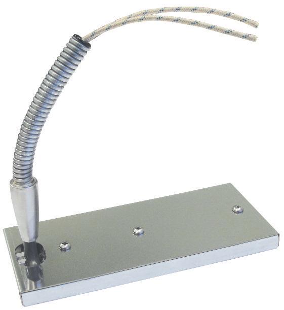 |
| E1 Style Tubular ends folded at a right angle with Stainless-steel braids which provide strength and protect leads from abrasion. Sharp bends are possible with this type of lead. |  |
| E2 Style Tubular ends exiting straight from the edge of the strip heater with stainless-steel braids. To prevent failures, leads should never be pulled or used as transportation handles. |  |
| G1 Style NEMA-1 enclosures provide protection against exposed electrical wiring and terminals. Enclosure dimensions can change with heater size. |  |
channel strip heaters are reliable flat heating cells, designed to provide efficient heat to flat surfaces and in space heating applications. The thick rectangular stainless housing of these heaters provides a rugged construction suitable for industrial applications. Finned channel strip heaters have relatively larger exposed surfaces compared to regular channel heaters. This makes them highly efficient in transferring heat in both natural and forced convection space heating.
The housing of a channel strip heater is 0.375” x 1.5” stainless steel rectangular tubing. Coiled Nickel-Chrome wire is placed inside special ceramic tiles. The terminals are secured with ceramic and mica insulators to the sheath. In order to improve their heat transferring capability and to make them vibration-resistant, channel strip heaters are filled with magnesium oxide powder that is compacted through vibration. Channel strip heaters are made with or without slotted mounting tabs.
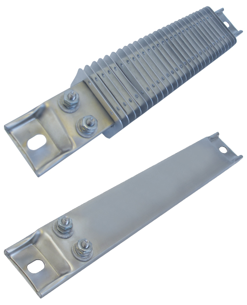
Finned channel strip heaters utilize 2” x 1.375” Aluminized steel fins (Stainless steel optional) that are designed in such a way that they grip the channel heater housing and dissipate heat efficiently.


To be able to use these ceramic insulators, strip heaters should have 1/2” x 5/8” mounting slots (factory pre-punched upon request).