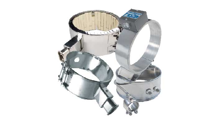
Used to heat (mostly) cylindrical surfaces and are available in several construction styles to perform under different operating environments. Band heaters can be found in several types of dimension, wattage, voltages and materials.
Mica band heaters are made with high-grade mica; the type and thickness of each mica insulating layer is carefully selected to provide excellent thermal conductivity and high dielectric strength. Similarly, to create a uniform heat distribution throughout the heater and to maintain the lowest possible resistive circuit temperature, an optimum combination of resistance ribbon alloy, cross-section and length is selected to design the resistance winding of each heater.
To maximize the surface-to-surface contact, mica band heaters are carefully rounded and formed to optimize the grip on a machine barrel. The external metallic protective sheath of the heater is made from a special alloy, which expands relatively less than when heated. The difference in thermal expansion makes the heater grip the barrel firmly once it is energized. This improves heat transfer which extends the life of the mica band heater.
The durability and performance of a heater depends on selecting the appropriate wattage. Exceeding the maximum allowable watt density for the specified heater size will result in premature heater failure. While calculating watt densities, we should remove the area of the cold section from the overall calculated surface area of the heater.

| Construction | Cold Section |
|---|---|
| One piece | 1″ x width |
| Two piece | 2″ x width |
| Holes, Cutouts | (Size + 1/2″) x width |


Band heaters are available with various types of electrical terminations. Each termination has its own unique characteristics, advantages and limitations. When selecting a termination style, the following factors must be taken into consideration: diameter, width, voltage, amperage, operating temperature, electrical safety and cost.
Stainless steel screw terminals are the most convenient and economical means to connect a heater to an electrical power source. They are mostly recommended when high amperages (up to 25 amps) are involved. The temperature limitation is 840° F. We offer different screw terminal styles.

 |  |  |
| A Style Separate on opposite sides of the gap Screws have 3/4″ height above the barrel | B1 Style Along the width side by side Screws have 3/4″ height above the barrel | B2 Style Along the length side by side Screws have 3/4″ height above the barrel |
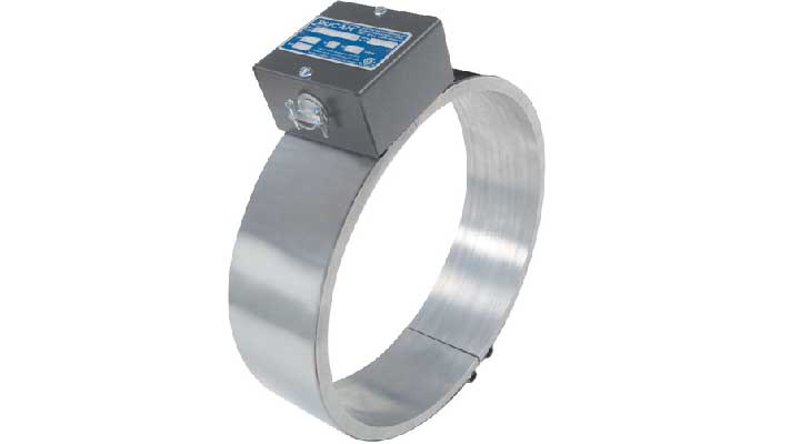
Terminal boxes eliminate the risk of electrical shock and electrical short by enclosing the terminals in a heavy-duty stainless steel box. Cover boxes come in two sizes, G1 and G2. For three-phase and dual voltage applications, special boxes are used.
| W | L | H | |
| G1 | 1 5/8″ | 2″ | 1 5/8″ |
| G2 | 2″ | 1/4″ | 1 3/4 |

CCeramic terminal covers provide a cost effective means of reducing the risk of electrical shock and electrical shorts.

High temperature wire is internally connected to the heater. This provides a safer electrical connection. However, it is physically impossible to conceal heavy gauge wire under the top metallic sheet. This limits the maximum amperage applicable to 20 Amps. Bucan offers different lead wire termination styles. Within each style there are different models of lead wire exits.
Within each style, there are different models of lead wire exits.
Armor cable provides the best protection against abrasion where a great deal of flexibility is not required. Straight lead exit or a 90° bend are the available options for this lead type. Brass fittings are used to secure the termination.
 |  |
| H Style – straight lead exit | GM Style – 90° bend |
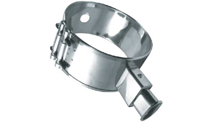
In applications where there is frequent movement or risk of abrasion, stainless steel braided leads are recommended. Heat shrink sleeving at the end of the leads prevents the braid from fraying.
 |  |  |  |
| E Style Straight lead exit | LP Style Low profile terminal cover | C Style Used mostly with nozzle heaters | I Style 180° from gap |
Plain leads are used where there is no risk of abrasion or contamination. High temperature wire with fiberglass insulation (840° F) is standard. Teflon insulated wire is also available.
 |  |  |  |
| EF Style Straight lead exit | F Style Exiting on both sides of the gap | CF Style Used mostly with nozzle heaters | IF Style 180° from gap |
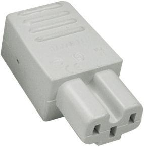
European plugs are safe and simple to use. They provide a quick solution in applications where the electrical termination has to be disconnected frequently. They can be used on all our construction and clamping styles. EP terminals provide practical electrical connections when a failed heater has to be replaced. European plugs are available either with two round prongs (6 mm.) or three flat prongs (one of which is a ground).
 |  |  |  |
| K90 Style tangential box | K00 Style vertical box | K45 Style 45° box | K3P Style 3 Prong with ground |
Maximum performance and ease of installation are two major considerations when selecting the construction style of a mica band heater. The following are the most common construction styles.
| ONE PIECE One-piece construction is used when a band heater can be installed on a barrel without extensively expanding it. Diameter:5/8″min;22″max Width: 5/8″ min; 14″ max |  |
| TWO PIECE OR MORE Two or more pieces are for ease of installation for a mica heater. A practical choice when the barrel diameter is large. Diameter:2″min;44″max Width: 5/8″ min; 14″ max |  |
| ONE PIECE FLEXIBLE One-piece flexible mica heaters are used in applications where two-piece construction is not practical, and expanding the heater is necessary during installation. These heaters should not be opened more than twice. |  |
| PARTIAL Partial band heaters are recommended where obstructions or complicated holes prevent having complete coverage on the surface of the barrel. |  |
| CONICAL Conical or irregular shaped mica heaters are made to fit unconventional forms. Heat transfer considerations impose limitations on the overall design and construction of these heaters. Our engineers are available to discuss the requirements of each application. |  |
| SQUARE AND RECTANGULAR Mica heaters can be made square, rectangular or multi-sided to suit your specific requirements. |  |
| REVERSE Reverse mica heaters are used in applications where heating from inside the barrel is required. The outside shell of these heaters is the heating surface and all the terminations and clamps are located on the inside of the heater. Diameter:3″min;36″max Width: 1″ min; 12″ max |
The efficiency of heat transfer from a heater to the medium it is intended to heat is the most important factor that determines heater longevity. The quality of heat transfer from a mica band heater to the application surface, which is mostly through conduction, depends on the heater clamping mechanism.
Bucan mica band heaters come with different clamping styles. Each style has unique characteristics and advantages. Selection is based on the specific requirements of the application. For assistance in selecting the best available option, contact Bucan.
| INDEPENDENT STRAP These straps evenly distribute the drawing force around the band heater by clamping the heater tightly around the surface of the cylinder. This distributed force is transferred to the internal windings, improving heat transfer through effective surface contact and elimination of air gaps. |  |
| BUILT-IN BARREL NUTS This clamping mechanism combines the drawing quality of an independent strap with ease of installation. The top sheet is transformed into a strap by incorporating barrel nut fasteners at both sides of the gap. Recommended when holes and cut-outs prevent the usage of an independent strap. |  |
| SPOT-WELDED STRAPS This construction is similar to the built-in barrel nut style. The fastener section of an independent strap is spot welded on the top sheet on both sides of the gap. This construction allows for a heated section under the fastener. |  |
| FLANGE LOCK-UP The most economical fastening style, flange lock-up is used mostly on narrow heaters. |  |
| WEDGE-LOCK Low profile clamp. Used when clearance above the heater is limited. A wedge-like clamp slides on the lips of the heater located on both sides of the gap. The normal height from the inner diameter (ID) to the highest point of the wedge lock is 5/16”. |  |
| LATCH AND TRUNION Ideal when fast detachment is required. The clamp is released with a flip of the thumb, eliminating the usage of any tools. The spring loaded 1/4-20 bolt absorbs thermal expansion in the fastened position. |  |
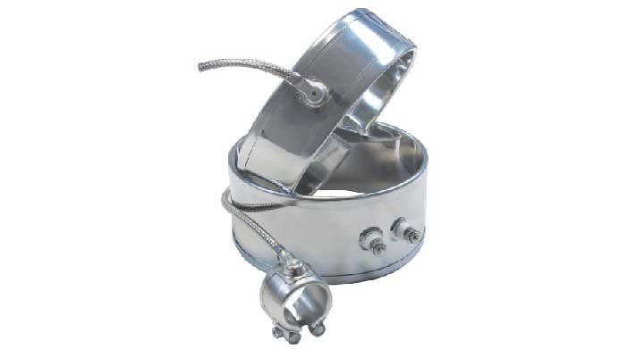
| HINGES Used when a heater band has two sections. A piano hinge is incorporated on one side of the heater, while the other side can have any kind of clamp. The clearance between the two sections on the side of the hinge is 5/16“. |  |
| SPRING-LOADED BARREL NUTS Independent straps, built-in barrel nuts and spot welded straps can have longer screws with incorporated die springs. These springs help to keep the band heater tight during thermal expansion. Only available in 1/4-20 screws. |  |
| CLAMPING PADS Mostly used in two section partial heaters. When an obstruction prevents the usage of a complete band heater, it becomes necessary to create a large gap and fasten the heater to the cylinder on both sides of the gap. It is not advisable to have clamping pads on both sides of the same section of a heater, because thermal expansion might detach the heater from the cylinder. |  |
| REVERSE CLAMPING This mechanism expands the diameter of a heater and is used with heaters that are made to heat the inside surface of a cylinder. |  |
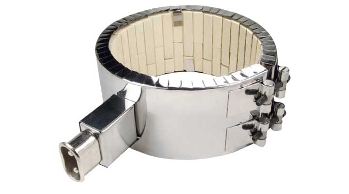
An additional advantage of Ceramic heaters is that they transfer heat through conduction and radiation. This makes their tightness on barrels less critical; thus, they are less prone to thermal expansion problems. It should be noted that over-tightening a ceramic heater increases the pressure on the ceramic fiber mat, which reduces its insulating efficiency. Therefore it should be avoided. Theoretically, there are no restrictions on the diameter that ceramic heaters can attain; however, because these heaters utilize ceramic tiles that are available only in specific lengths, the width of these heaters falls within a certain incremental range of sizes.
Ceramic band heaters are available with different clamping mechanisms, termination styles, holes and cut-outs.
It should be noted that over-tightening a ceramic heater increases the pressure on the ceramic fiber mat, which reduces its insulating efficiency. Therefore it should be avoided. Theoretically, there are no restrictions on the diameter that ceramic heaters can attain; however, because these heaters utilize ceramic tiles that are available only in specific lengths, the width of these heaters falls within a certain incremental range of sizes. Ceramic band heaters are available with different clamping mechanisms, termination styles, holes and cut-outs.

| Max Temperature | 1200°F |
| Max Voltage | 600V |
| Maximum watt density | 45 w/in² |
| Wattage Tolerance | +5%, -10% |
| Minimum diameter | 2″ |
| Minimum width | 1″ |
| Thickness with 1/4″ insulation | 5/8″ |
| Standard gap | 3/8″ |
| Sheath Material | Stainless Steel 430 |
| K00 Style – European connector: Ideal termination style when the power leads are frequently removed from the heater. |
 |  |
| G Style – Terminal box: A practical way to protect screw terminals from damage and exposure. | B Style – Post terminals: The most commonly used termination style. Recommended for high amperage applications |
 |  |
| H Style – Straight armor cable: Provides protection against abrasion and contamination | E Style – Stainless steel braid: Highly flexible. Protects the lead wire from abrasion |
 |  |
| K90 Style – European connector: Used when there is not enough clearance above a heater to use the K00 style European connector. | K00 Style – European connector: Ideal termination style when the power leads are frequently removed from the heater. |


Ceramic heaters can be combined with high velocity fans to form fast responding heat/cool units in accurate heating applications. These heaters are made with a perforated outside stainless steel sheath, and with no insulating jacket.
| Flange lock-up The most economical clamping style for ceramic heaters, with #10-32 nuts and screws. |  |
| Latch & trunion: Available on heaters that are 10” or bigger in diameter. This clamping style provides ease of installation and removal. |  |
| Barrel nuts: Barrel nut fasteners with 1/4-20 socket head screws are standard on all ceramic heaters. This style can accommodate springs which compensate for thermal expansion. |  |

Maximum temperature: 1400ºF
Max ID for one piece construction: 14″
Max ID for two piece construction: 26″
Max width: 6″
Gap: 1/4″ to 3/4″ depending on width
Max width for heaters less than 3″: Twice the diameter
Max voltage: 480V
Max amps for leads: 10 Amps
Max amps for screw terminals (10-32 UNF): 22 Amps
Sheath Material: Stainless Steel 430
| B1 Style Post terminals (10-32 UNF) placed along the width of the heater side by side |  |
| B2 Style Post terminals (10-32 UNF) placed Along the length of the heater side by side. |  |
| G-STYLE – TERMINAL BOX Post terminals (10-32 UNF) placed inside a heavy duty stainless steel terminal box that eliminates the risk of electrical shock and shorting. |  |
| LP Style Low profile terminal cover for stainless steel braided high temperature leads. The orientation of the leads could be across the width or parallel to the circumferential length of the heater. |  |
| E Style Stainless steel braided high temperature leads exiting vertically on the surface of the heater. |  |
| H Style A flexible steel hose protecting high temperature leads exiting vertically on the surface of the heater |  |
| K00 Style European plug placed on a terminal box in a vertical position vertical with box |  |
| K90 Style European plug with a terminal box placed in a 90° position. |  |
| Termination | Min. ID (in) | Min. Width (in) |
| B1 | 2 | 2 |
| B2 | 2 | 1.5 |
| G | 4 | 1.5 |
| LP | 1.5 | 1.5 |
| E | 1.5 | 1.5 |
| H | 2 | 2 |
| K00 | 4 | 1.5 |
| K90 | 4 | 1.5 |
| One piece construction To secure good clamping and efficient heat transfer, recommended width 2in -3in. |  |
| Two piece construction To facilitate the installation on a barrel. This construction type is recommended either for heaters having internal diameters above 14in. Max ID 26in. |  |
| Hinged construction Two piece construction heaters with a hinge on one side. The terminals of these heaters are made 90° with respect to the gap or next to the gap. |  |
| Expandable construction Two piece construction heaters that have a common top sheet. This construction type allows the opening of the heater in order to install it on a barrel. The terminals of these heaters are made 90° with respect to the gap or next to the gap. |  |
| Holes and Cutouts Mineral insulated heaters can incorporate holes and cut outs with certain dimensional restrictions. |  |
| Construction | ID (in) | Width (in) | ||
| Max. | Min. | Max. | Min. | |
| One-piece | 14 | 1 | 6 | 1 |
| Two-piece | 26 | 3 | 6 | 1 |
| Expendable | 14 | 3 | 6 | 1.5 |
| Hinged | 26 | 6 | 6 | 1.5 |
The chart (seen above) is a watt-density selection guide for different heater diameters.
The following points should also be considered.
| Max. Temperature | 650°F |
| Max. Voltage | 300V/Section |
| Max. Watt Density | 40 w/in² Element Sheath |
| Wattage tolerance | +5%, -10% |
| Min. ID for Widths 1.5″ & 2.5″ | 3.5″ |
| Min. ID for Widths 3″ & 4″ | 5″ |
| Thickness | 1/2″ |
| Gap up to 11″ | 1/4″ |
| Gap above 11″ | Depends on ID |
| B Style The standard termination for Aluminum Band Heaters is the terminal lug with a 10-32 binder head screw. Terminal jumpers are available for easy wiring installations. |  |
| E Style Stainless-steel braids provide strength and protect leads from abrasion. However, leads should never be pulled or used as transportation handles. |  |
| H Style Encasing cables in metallic flexible tubing is the ideal method to protect leads from abrasion and contamination. Sharp bending is not possible with this type of leads. |  |
| T Style Teflon leads with Teflon heat shrink sleeves provide excellent protection against moisture and contamination. The temperature limitation for this type of leads is 500°F. |  |
| G1 Style NEMA-1 enclosures provide protection against exposed electrical wiring and terminals. Enclosure dimensions can change with heater size. |  |
| G4 Style Aluminum Band heaters can have NEMA-4 moisture and contamination proof enclosures which are brazed or welded to the tubular elements. |  |
| Partial Partial Aluminum Band Heaters are recommended where obstruction or complicated holes prevent complete coverage on the surface of the barrel. |  |
| Insulated To prevent energy loss, Aluminum Band Heaters can have separate insulating shrouds. These shrouds are custom-made as per heater specs. |  |
| Reverse Reverse constructions are for applications that require internal heating. Electrical terminations and reverse clamping mechanisms are located on the inside of the heater. |  |