Maximum Pressure – 150 psi (10.3 bar)
Maximum Operating Temperature – 250°F / 121°C
Normal Working Air Pressure – 80 to 100 psi
Pressure Drop Across Purge Valve – 1 psi at 50 gpm
Body – Glass Filled Nylon
Valve Disc – Stainless Steel
O-Rings – EPDM
Check Valve – Brass
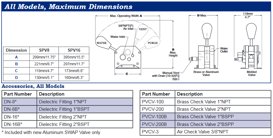
| Model | Thread Size | SWAP Model | Weight |
|---|---|---|---|
| SPV8-A-M | 1″ NPT | Standard | |
| SPV8-L-M | 1″ NPT | With Locking Pin | 2.5kg |
| SPV8B-A-M | 1″ BSPP | Standard | 5.5lbs |
| SPV8B-L-M | 1″ BSPP | with Locking Pin |
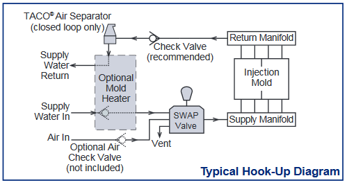
An included check vlve should be installed in the return line downstream from the “Return Manifold” to prevent backflow to the mold.
Tubing may be connected to the manual vent drawing port so any residual water after the purge cycle can be drained into a container or drain.
An optional spring-loaded, locking pin is available for molder who require two hand operation. This prevents accidental valve handle movement.
The SWAP Valve is well-suited for cooling water supply lines up to 2 inches NPT. It is permissible to adapt 2/4″, 1-1/4″, and 1-1/2″ line sizes providing adequate cooling water flow can be achieved.
Typical mounting is on the press frame on the safety door frame. Mounting on any suitable surface, such as a platen, mold or manifold stand is acceptable.
| For Normal Processing | Select WATER. Cooling Water is available to the supply manifold. Purge Air is blocked. |
| To Evacuate Cooling Water | Select PURGE. Purge Air is available to the Supply manifold. Cooling Water is blocked. |
| To Bleed-Off Trapped Pressure and Drain Residual Water | Select VENT. Press Manual Vent-Drain Valve. Purge air is blocked, cooling water is blocked. |
Installation of an air separator in the return line of a closed loop cooling system is recommended.