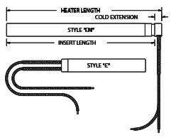
The “C” and “CN lead configurations consist of stranded lead wire externally crimp connected to the solid pins exiting the heater. Style “C” leads exit straight out the end of the cartridge while the leads of the style “CN” exit out the side of the sheath at 90 degrees. The lead end of the style “CN” is covered by a welded in end cap. The pin and connection area of both styles are sheathed in an insulating layer of silicone rubber coated Fiberglass sleeving. Standard lead insulation is rated at 842 °F/450 °C continuous wire temperature. Both “C” and “CN” lead styles are best suited to applications where lead flexing is minimal. A lead length of 10 inches, including the solid pin extension, is standard. When ordering, specify “C” or “CN” leads and the desired lead length.
| Cartridge Dia | 1/4″ | 5/16″ | 3/8″ | 1/2″ | 5/8″ | 3/4″ | 1″ |
| Extension | .250 | .250 | .250 | .250 | .312 | .312 | .375 |

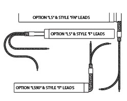
The “F” and “FN” style leads are internally connected to provide a fully flexible lead exit from the ceramic end cap. Style “F” leads exit straight out the lead end of the cartridge while the leads of the style “FN” exit out the side of the sheath at 90 degrees. The lead end of the style “FN” is covered by a welded in end cap. Standard lead insulation is rated at 842 °F/450 °C continuous wire temperature. Style “F” and “FN” leads can be bent sharply at the ceramic end cap without exposing or breaking the conductor and are popular in applications where the lead exit area is restricted. A lead length of 10 inches is standard. When ordering, specify “F” or “FN” leads and the desired lead length.
| Cartridge Dia | 1/4″ | 5/16″ | 3/8″ | 1/2″ | 5/8″ | 3/4″ | 1″ |
| Extension | .250 | .250 | .250 | .250 | .312 | .312 | .375 |
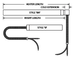
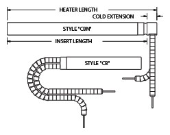
The “B” and “BN” style leads feature full flexible leads with protective stainless steel overbraid. Style “B” leads exit straight out the lead end of the cartridge while the style “BN” leads exit out the side of the sheath at 90 degrees. The lead end of the style “BN” is covered by a welded in end cap. Standard lead insulation is rated at 842 °F/450 °C continuous wire temperature. Style “B” and “BN” leads are popular in applications where external wiring is required and where some additional protection is necessary. A lead length of 12 inches with 10 inches of braid is standard. Unless otherwise specified, leads are 2 inches longer than the requested braid length. When ordering, specify “B” or “BN” leads and desired lead and braid length.
| Cartridge Dia | 1/4″ | 5/16″ | 3/8″ | 1/2″ | 5/8″ | 3/4″ | 1″ |
| Extension | .375 | .375 | .375 | .375 | .437 | .437 | .500 |
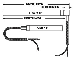
The “BR” and “BRN” style leads feature flexible leads with protective stainless steel overbraid externally crimped to the heater. Style “BR” leads exit straight out the lead end of the cartridge while the style “BRN” leads exit out the side of the sheath at 90 degrees. The lead end of the style “BRN” is covered by a welded in end cap. Standard lead insulation is rated at 842 degrees F / 450 degrees C continuous wire temperature. Style “BR” and “BRN” leads are useful where protection is required and a rigid lead exit is preferred. A lead length of 12 inches with 10 inches of braid is standard. Unless otherwise specified, leads are 2 inches longer than the braid length. When ordering specify “BR” or “BRN” leads and desired lead and braid length.
| Cartridge Dia | 1/4″ | 5/16″ | 3/8″ | 1/2″ | 5/8″ | 3/4″ | 1″ |
| Extension | .375 | .375 | .375 | .375 | .437 | .437 | .500 |
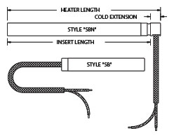
The “SB” and “SBN” style leads feature flexible leads with a single protective silicone fiberglass sleeve over both leads. Style “SB” leads exit out the side of the sheath at 90 degrees. The lead end of the style “SBN” is covered by a welded in end cap. Standard lead insulation is rated at 842 F / 450 C continuous wire temperature. The silicone coating of the fiberglass sleeve will degrade at temperatures in excel of 600 F / 316 C. Style “SB” and “SBN” leads are used where some lead protection is desired. A lead length of 12 inches with 10 inches of Sleeving is standard. Unless otherwise specified, leads are 2 inches longer than the sleeve length. When ordering specific “SB” or “SBN” leads and desired lead and sleeve length.
| Cartridge Dia | 1/4″ | 5/16″ | 3/8″ | 1/2″ | 5/8″ | 3/4″ | 1″ |
| Extension | .375 | .375 | .375 | .375 | .437 | .437 | .500 |
The “SE” and “SEN” style leads feature flexible leads with a single protective silicone fiberglass sleeve over both leads. Style “SE” leads exit straight out the lead end of the cartridge while the style “SEN” leads exit out the side of the sheath at 90 degrees. The lead end of the style “SEN” is covered by a welded in end cap. Standard lead insulation is rated at 842 F / 450 C continuous wire temperature. The silicone coating of the fiberglass sleeve will degrade at temperatures in excess of 600 F / 316 C. Style “SE” and “SEN” leads are used where some lead protection is desired. A lead length of 12 inches with 10 inches of Sleeving is standard. Unless otherwise specified, leads are 2 inches longer than the sleeve length. When ordering specific “SE” or “SEN” leads and desired lead and sleeve length.
| Cartridge Dia | 1/4″ | 5/16″ | 3/8″ | 1/2″ | 5/8″ | 3/4″ | 1″ |
| Extension | .375 | .375 | .375 | .375 | .437 | .437 | .500 |
 ol-md-4″>
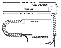
The “A” and “AN” style leads feature full flexible leads with protective stainless steel armor. Style “A” leads exist straight out the lead end of the cartridge while the style “AN” leads exist out the side of the sheath at 90 degrees. The lead end of the style “AN” is covered by a welded in end cap. Standard lead insulation is rated at 842 F / 450 C continuous wire temperature. Style “A” and “AN” leads are popular in applications where external wiring is required and additional protection is necessary. A lead length of 13 inches with 10 inches of armor is standard. Unless otherwise specified, leads are 3 inches longer than the armor length. When ordering specify “A” or “AN” leads and desired lead and armor length.
| Cartridge Dia | 1/4″ | 5/16″ | 3/8″ | 1/2″ | 5/8″ | 3/4″ | 1″ |
| Extension | .375 | .375 | .500 | .500 | .625 | .625 | .750 |
| O.D. (Max) | .207 | .244 | .275 | .345 | .437 | .493 | .623 |
The “CT” and “CTN” style leads feature flexible leads and a totally sealed stainless steel convoluted tubing style armor silver solder sealed to the heater. Style “CT” leads exist straight out the lead end of the cartridge while the style “CTN” leads exist out the side of the sheath at 90 degrees. The lead end of the style “CT” is covered by a welded in end cap. Standard lead insulation is rated at 842F / 450C continuous wire temperature. Style “CT” and “CTN” leads are popular in applications where the heaters are constantly exposed to contaminants. A lead length of 13 inches with 10 inches of armor is standard. Unless other wise specified, leads are 3 inches longer than the armor length. When ordering specific “CT” or “CTN” lead and desired lead and armor length.
| Cartridge Dia | 1/4″ | 5/16″ | 3/8″ | 1/2″ | 5/8″ | 3/4″ | 1″ |
| Extension | N/A | N/A | N/A | .500 | .625 | .625 | .750 |
| O.D. (Max) | N/A | N/A | N/A | .426 | .426 | .570 | .570 |

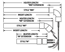
The “W” and “WN” lead configurations feature flexible leads exiting the cartridge through a protective wrot copper fitting. The style “W” leads exit the cartridge through a straight coupling while the style “WN” leads exit through a wrot copper elbow to provide a 90 degree lead exit. Standard lead insualtion is rated at 842F/450C continuous wire temperature. The style “W” and “WN” leads provide lead protecton and a positive stop to control heater insertion depth. The wrot copper fittings are also useful in applications where a silicone or epoxy potted seal is required. Lead length, measured from the fitting lead exit, is supplied as 10 inches standard. When ordering specific “W”, “WF” or “WN” and lead length.
| Cartridge Dia | 1/4″ | 5/16″ | 3/8″ | 1/2″ | 5/8″ | 3/4″ | 1″ |
| Extension | 7/8 | 3/4 | 3/4 | 7/8 | 1 1/8 | 1 3/8 | 1 7/8 |
| W Extension | 1 | 1 1/8 | 1 1/16 | 1 1/4 | 1 5/8 | 1 7/8 | 2 7/8 |
| WF Extension | 7/8 | 1 | 15/16 | 1 1/8 | 1 7/16 | 1 7/8 | 2 7/8 |
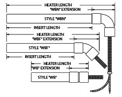
The “WB” and “WBN” lead styles are stainless steel wire braid protected and exit from a protective wrot copper fitting. The style “WB” braid protected leads exit the cartridge from a straight coupling, the “WBF” from a 45 degree elbow and the style “WBN from a 90 degree elbow. Standard lead insualtion is rated at 842F 450C continous wire temperature. “WB”, “WBF” and “WBN” lead systems provide substantial lead protection and a positive stop to control heater insertion depth. The fitting is also useful in applications where a silicone or epoxy seal is required. Standard leads are 13 inches with 10 inchdes of wire braid, as measured from the fitting lead exit. Unless otherwise specified, leads are 3 inchdes longer than the braid length. When ordering , specific “WB”, WBF, or WBN lead length and braid length.
| Cartridge Dia | 1/4″ | 5/16″ | 3/8″ | 1/2″ | 5/8″ | 3/4″ | 1″ |
| WB Extension | 7/8 | 3/4 | 3/4 | 7/8 | 1 1/8 | 1 3/8 | 1 7/8 |
| WBF Extension | 1 | 1 1/8 | 1 1/16 | 1 1/4 | 1 5/8 | 1 7/8 | 2 7/8 |
| WBN Extension | 7/8 | 1 | 15/16 | 1 1/8 | 1 7/16 | 1 7/8 | 2 7/8 |
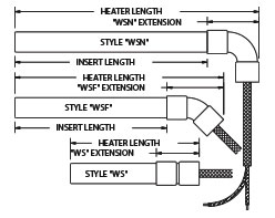
The “WS”, “WSF” and “WSN” lead styles are silicone sleeve protected and exit from a protective wrot copper fittings. The style “WS” sleeved leads exit the cartridge from a straight coupling, the “WSF” from a 45 degree elebow and the style “WSN” from a 90 degree elebow. Standard lead insulation is rated at 842 F/450C continuous wire temperature. “WS”, WSF” and “WSN” lead systems provide moderate lead protection and a positive stop to cotnrol heater insertion depth. The fitting is also useful in applications where a silcone or epoxy seal is required. Standard leads are 13 inches with 10 inches of wire braid, as measure from the fitting lead exit. Unless otherwise specified, leads are 3 inches longer than the braid length. When ordering, specifc “WS”, “WSF” or “WSN” lead length and braid length.
| Cartridge Dia | 1/4″ | 5/16″ | 3/8″ | 1/2″ | 5/8″ | 3/4″ | 1″ |
| WB Extension | 7/8 | 3/4 | 3/4 | 7/8 | 1 1/8 | 1 3/8 | 1 7/8 |
| WBF Extension | 1 | 1 1/8 | 1 1/16 | 1 1/4 | 1 5/8 | 1 7/8 | 2 7/8 |
| WBN Extension | 7/8 | 1 | 15/16 | 1 1/8 | 1 7/16 | 1 7/8 | 2 7/8 |
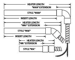
The “WA” and “WAN” lead styles are stainless steel armor protected and exit from a protective wrot copper fitting. The style “WA leads exit the cartridge through a straight coupling, while the style “WAN” armor protected leads exit through a copper elbow to provide a 90 degree lead exit. Standard lead insulation is rated at 842F / 450C continous wire temperature. “WA” and “WAN” lead systems provide substantial lead protection and a positive stop to control heater insertion depth. The fitting also accommodates silicone ad epoxy potting when required. Standard leads are 13 inches with 10 inchdes of armor, as measure from the fitting lead exit. Uness otherwise specified, leads are 3 inches longer than the armor length. When ordering specific “WA”, “WF” or “WAN” lead length and armor length.
| Cartridge Dia | 1/4″ | 5/16″ | 3/8″ | 1/2″ | 5/8″ | 3/4″ | 1″ |
| WA Extension | 7/8 | 7/4 | 1 | 1 3/16 | 1 1/4 | 1 1/2 | 1 7/8 |
| “WAF” Extension | |||||||
| WAN Extension | 1 1/16 | 1 1/16 | 1 3/8 | 1 5/8 | 2 1/16 | 2 1/8 | 2 7/8 |
| Armor OD (Max) | 1/4 | 5/16 | 3/8 | 1/2 | 5/8 | 5/8 | 1 |
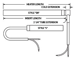
The “S” and “SN” SJO electrical cord style leads provide additional lead protection and moisture resistance in applications where leads are exposed to temperatures below 150 F. Depending on the application a 2 to 3 inch cold section may be required to insure that the SJO cable is operating below the maximum temperature limit. Style “S” leads exit straight out the lead end of the cartridge while the leads of the style “SN” exit out the side of the heat at 90 degres through a protective extension tube. The lead end of the style “SN” is covered by a selded in cap. Style “SP” and “SNP” are similar but include a molded plug. The SJO cable lead styles are particularly useful in applications such as crankcase heating and food processing equipment, where the heater leads may be exposed to liquid contamination. Standard leads include consist of 36 nches of SJO cable. When ordering, specific “S” or “SN” leads and required cable length. If a molded on plug is required, specific “SP” or “SNP” and the required cable length.
Cartridge Dia
| 1/4″ | 5/16″ | 3/8″ | 1/2″ | 5/8″ | 3/4″ | 1″ | |
| Extension | .375 | .375 | .375 | .375 | .437 | .437 | .500 |
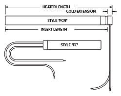
The “FC” and “FCN” style leads provide extended life in applications where severe flexing of leads is unavoidable. The lead conductors consist of flexible stainless teel stranded cable. Style “FC” leads exit straigt out the lead end of the cartridge while the leads of the style “FCN” exit out the side of hte sheat at 90 degrees. The lead end of the style “FCN” is covered by a welded in cap. The lead styles “FC” and “FCN” are particularly useful in applications such as sealing bars, where the heater leads must withstand constant flexing. “FC” and “FCN” leads can be combined with wire braid or armor for additional lead protection. Standard leads are teflon insulated but can also be supplied with fiberglass insulation or mica tape insulation. When ordering, specific “FC” or “FCN” leads and note any special insulation or lead protection. The stainless steel lead conductor reduces the total current capcity of the leads and can make this lead style impractical on larger high wattage heaters.
| Cartridge Dia. | 1/4″ | 5/16″ | 3/8″ | 1/2″ | 5/8″ | 3/4″ | 1″ |
| Extension | .250 | .250 | .250 | .250 | .312 | .312 | .375 |
The “CB” and “CBN” style leads provide a customer specified length of solid pin leads with high temperature ceramic bead insulation. Style “CB” leads exit straight out the lead end of the cartridge while leads of the style “CBN” exit out the side of the sheath at 90 degrees. The lead end of the style “CBN” is covered by a welded in cap. The lead styles “CB and CBN are intended for applications where the heater leads ar eexposed to temperatures exceeding the rating of the standard lead inuslation “B” and CBN leads are often combined with an additional length of crimped on conventional leads. Standard leads include 6 inches of beads on 8 inch pins. When ordering, specific “CB” or “CBN” leads, ermaic bead length and required pin length. Include any crimp connected lead length desired.
| Cartridge Dia. | 1/4″ | 5/16″ | 3/8″ | 1/2″ | 5/8″ | 3/4″ | 1″ |
| Extension | .375 | .375 | .375 | .375 | .437 | .437 | .500 |
The standard “PT” and “PTN” post terminals consists of stainless steel terminals securely welded to the pins exiting the heater and are available on heaters 1/2 inch or more in cross section. Special versions of the post terminal termination utilizing terminal blocks are available for all square cartridge sizes. The post terminal lead system provides a secure external termination for heaters installed in hard wired electrical systems where simple removal of individual heaters without disturbing the wiring. Standard post terminal configurations will be supplied on square cartridges 1/2 inch or larger unless otherwise specified. When ordering, specific “PT” or “PTN” termination. Include a sketch or description of any special terminal dimensions and thread specifications.
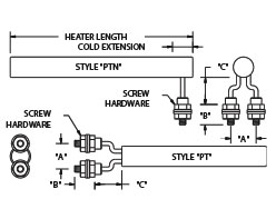
The “ST” and “STN” style terminations feature attached male spade connectors. The quick connect spade connectors are available in range of standard sizes and configurations and can be attached to any of the square cartridge sizes. The style “ST” and “STN” termiantions provide convenience in applications where the frequent connection and disconnection of the heater is required. When ordering specific style “ST” or “STN” termination and note any special spade terminals size or design required. Include a sketch or description of any terminal dimensions and thread specifications. Leads with matching female connectors can also be supplied. If required, please include the required lead type and lead length when placing your order.

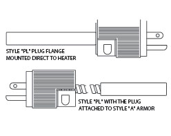
The “PL” style lead termination features an attached male plug with a nylon dead front design and molded-in cord grip. Available plugs include straight and twist lock blade types in both grounded and ungrounded versions. The style “PL” plug termination can be attached to any of the protected lead configurations. The style “PL” termination is primarily intended for those applications where the frequent connection and disconnection of the heater is required. When ordering, specific style “PL” termination and provide a complete descr8iption of the plug or the manufacturers plug catalog number desired. Please also include the required lead style and lead lengths when placing your orders.
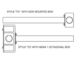
The “TO, “TM” and “TE” electrical box terminations feature electrical box enclosures mounted to the lead end of the heater. Box style terminations enclose the heater lead connections and provide application environmental protection. Style “TO” features a standard NEMA 1 octagonal box, style “TM”: a NEMA 4 moisture-proof box and style “TE” a NEMA 7 explosion proof box. Style “T”, “TM” and “TE” terminations are useful in applications where eternal wiring must conform to specific wiring cods or in applications where additional protection of electrical connections is necessary. When ordering, specific “TO, “TE” or “TE” box termination and desired terminal or lead style. If a specific box is required please provide a complete description or manufacturers box catalog number.
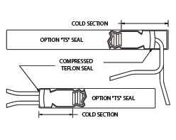
The style “TS” lead seals feature a swaged in teflon seal plug and teflon leads. The resulting lead construction provides a contamination resistant seal which reduces the possibility of contamination from liquids such as water and oil. The teflon seal is most effective in applications where the seal is exposed to temperatures below 275 F. Depending on the application a 1 inch or longer cold section may be required to insure the teflon seal and leads are maintained below recommended temperature limits. Teflon seals can be combined with the most standard lead styles. When ordering specify seal options “TS”. Please include desired lead style and length.
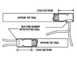
The style “SS” lead seals consist of silicone rubber sealant potted into a cavity at the lead end of the cartridge. The resulting seal construction reduces the possibility of contamination from liquids such as water and oil. The silicone rubber potted lead seal is most effective in application where the seal is exposed to temperatures below 450 F. Depending on the application a 1 inch or longer cold section may be required to insure that the silicone rubber seal and leas are maintained below recommended temperature limits. Silicone rubber seals can be combined with most standard lead styles. When ordering specific seal option “SS”. Please include desired lead style and length.
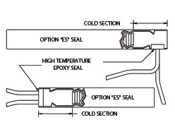
The style “ES” lead seals consist of high temperature epoxy potted into a cavity at the lead end of the square cartridge. The epoxy sealed lead construction provides both contamination and abuse resistance. The seal reduces the possibility of contamination and abuse resistance. The seal reduces the possibility of contamination from liquids such as a water and oil. The standard epoxy seal is most effective in applications where the seal is exposed to temperatures below 500F. Epoxy with temperature rating of 600F and 700F is available for higher temperature seal applications. Depending on the application a 1 inch or longer cold section may be required to insure that the epoxy seal is maintained below recommended temperature limits. Epoxy seals can be combined with most standard lead styles. When ordering specific seal option “ES”. Please include desired lead style and length.
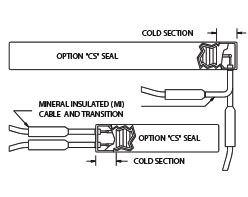
The style “CS” lead seals consist of two high temperature, single conductor, mineral insualted cables, braze sealed to the cartridge. Leads are terminated into sealed transition fitting on each cable. The mineral insulated cable provides both contamination and physical abuse resistance. The seal reduces the possibility of contamination from liquids such as water and oil.. The sealed cable area at the end of the cartridge can withstand temperatures up to 1200F. This construction requires a 1/2inch cold section, in which to terminate the cable. Style “CS” seals can be combined with most standard lead styles. When ordering specific seal option “CS”. Please include cable length, desired lead insulation and lead lengths.
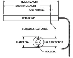
These industry standard mounting flanges provide a means of securing the cartridge in a fixed position to prevent movement and creep due to conditions of mild vibration and thermal cycling. Standard flanges are often used to mount various external wiring devices including electrical boxes and plugs. Nonstandard flanges featuring special shapes, sizes and mounting hold configuration can be supplied when required. Non-standard flanges featuring special shapes, sizes and mounting hole configurations can be supplied when required. Standard flanges are manufactured from 300 series stainless steel and conform to the dimensions shown in the table below. Flanges must be located over an unheated area. To order specific “MF” options and note the desired mounting location.
| Cartridge Dia. | 1/4″, 5/16, 3/8 & 1/2 | 3/8,1/2,5/8 & 3/4 | 5/8,3/4 & 1 |
| Flange Dia. | 1 | 1 1/2 | 2 |
| Hole Bolt Circle | .750 | 1.125 | 1.500 |
| Hole Dia. | .144 | .156 | .201 |
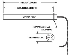
The standard stainless steel stop ring provides a means of locating a cartridge at a specific and consistent location within a ghrough drilled hole. By adding a drilled and tapped hole in close prximilty to the heater, an appropriate screw can be used to capture the stop ring edge and secure the cartridge in position. Stop rings are manufactured from 300 series stanless steel and conform to the dimensions listed in the below table. STop rings in special shapes and sizes can be supplied when required. Stop rings can be located at any position alon the length of the cartridge, but must always be placed over a cold area. To order, specific “MS” option and include the desired mounting location in your order.
| Cartridge Dia. | 1/4″ | 5/16″ | 3/8″ | 1/2″ | 5/8″ | 3/4″ | 1″ |
| Stop Ring Dia. | .500 | .562 | .625 | .750 | .875 | 1.000 | 1.250 |
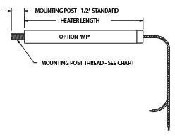
The threaded disc end mounting post provides an alternative method of securing a cartridge heater in place in a heated bloc. The addition of an appropriate size washer with a nut to secure it in place will prevent the cartridge from backing out of the hole. This mounting method is often used in conjunction with a stop ring to secure a heater in position in applications where space restrictions prohibilt the use of a mountain flange. The 1/2 inch long threaded post is securly attached to the heater and can also be used to assist in the removal of the cartridge for system maintenance. Standard mounting post thread specifications for various heater diameters are listed in the below table. To order, specific option “MP”.
| Cartridge Dia. | 1/4″ | 5/16″ | 3/8″ | 1/2″ | 5/8″ | 3/4″ | 1″ |
| Stop Ring Dia. | 8-32 | 8-32 | 10-24 | 1/4-20 | 1/4-20 | 3/8-18 | 3/8-18 |
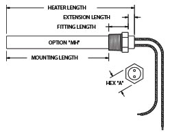
Standard hex head pipe fittings provide a leak resistant, cartridge mounting system for liquid filled container systems and piping. These fittings are also useful in securing heaters into non-immersion applications such as plattens and molds. Fittings can be located at any desired location but must always be located over unheated areas. STandard fitting location for straight lead styles is flush with the lead end of the heater, leaving no extension. Fitting location for 90 degree lead styles corresponds to the start of the standard lead extension. Fittings are available in brass, steel and stainless steel. Special fitting sizes and materials can be supplied when required. Please specify desired material and location when ordering.
| Cartridge Dia. | 1/4″ | 5/16″ | 3/8″ | 1/2″ | 5/8″ | 3/4″ | 1″ |
| Fitting NPT Thread | 1/8 | 1/4 | 1/4 | 3/8 | 1/2 | 3/4 | 1 |
| Fitting Length | .56 | .75 | .75 | .78 | .97 | 1.15 | 1.34 |
| hex “A” | 7/16 | 9/16 | 9/16 | 11/16 | 7/8 | 1 1/16 | 1 5/16 |
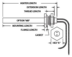
The bulkhead style fittings are useful in air and gas heating applications involving thin wall containers and can also be used to attach protective electrical boxes to the heater. Fittings can be positioned at any location but must be over an unheated zone. The standard fitting location for straight lead styles is flush with the lead end of the heater, leaving no extension. The 90 degree lead styles are not recommended due to difficulty of installtion. Fittings are available in brass, steel and stainless steel and are supplied complete with gasket, washer and nut. Special fitting sizes and materials can also be supplied if required. Please specify desired material bulkhead mounting location when ordering.
| Cartridge Dia. | 1/4″ | 5/16″ | 3/8″ | 1/2″ | 5/8″ | 3/4″ | 1″ |
| Fitting Thread Size | 1/2-20 | 1/2-20 | 1/2-20 | 5/8-18 | 3/4-16 | 1-12 | 1 1/4-12 |
| Thread Length | 3/4 | 3/4 | 3/4 | 1 | 1 | 1 1/4 | 1 3/4 |
| Flange Length | 3/16 | 3/16 | 3/16 | 1/4 | 1/4 | 3/8 | 3/8 |
| Hex “A” | 3/4 | 3/4 | 3/4 | 15/16 | 1 1/8 | 1 1/2 | 2 1/4/td> |
Cartridges can be centerless ground to precision diameter tolerances for improved cartridge to hold fit. This option is particularly useful in metal block heating applications where the cartridge is required to operate at the upper limits of its watt density capabilities. Please note that standard units are ground to a smaller than standard actual diameter. Diameter tolerances are held to +/- .0005 on centerless diameter. Diameter tolerances are held to +/- .0005 on centerless ground cartridge heaters. When ordering, specify Option “CG”. Cartridge heaters with finished diameters not shown in the table or with special diameter tolerances can be supplied. Please note any special requirements on your order
| Cartridge Dia. | 1/4″ | 5/16″ | 3/8″ | 1/2″ | 5/8″ | 3/4″ | 1″ |
| Precision Dia. | .241 | .302 | .363 | .488 | .613 | .738 | .984 |

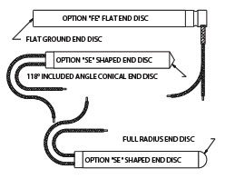
A Flat or shaped end disc configuratoin can be substituted for the normally concave end disc sealing the end of the cartridge. The flat and shaped end discs are commonly used to increase heat transfer into the entremities of an application by using a matching, flat bottomed or shaped hole. These options are useful in applications where process termpature at the end of the heated component is critical. These special end discs are often used in conjunctions with distributed wattage to insure heat uniformity. Common shape variations include a 118 degree included angle cone disegined to match the standard angle at the bottom of a drilled hole. When ordering please specify option “FE” or “SE”. When option “SE” is selected, please enclose a sketch or clear description of the required shaped end disc configuration.
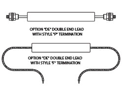
The double end lead termination provides an alternative lead connection system for heating applications with special wiring requirements. Common applications for the double end lead system include the assemblies requiring combinations of series and parallel wiring to bus termiantion system is typically supplied with post termianls but can be equiped with any desired lead configuration and protection system. The full range of eletrical and termal construciton options can be supplied in the double end termiantion configuration. Please specificy option “DE” and include the desired lead style and lead length in your order.
The lead support clip provides a simple and secure restraint system for the cartridge heater leads. A 3/4 inch long support clip is standrd on heaters less than 1/2 inch in diameter. A 1 1/4 inch long clip is used on heater 1/2 inch and large in diameter. Support clips normally exit at the same angle as the lead style selected. Other exit angles can be supplied on request. Support clips can be used with all plain, sleeved and wire braid protected lead styles. Lead support clips are useful in protecting leads from external stree and can be utlized as pull tabs to simplify heater removal for maintenance. Clip supports in special configuration or with mounting holes can be suplied if required. To order, specific “LS” option and include any special requirements Please include lead configuration in your order.
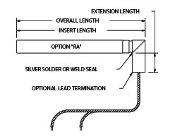
The “RA” construction option features a 90 degree tube extension securly brazed to the main sheath of the heater. This protective extension provides extra durability in applications where the lead exit area of the cartridge may be subject ot extreme abuse. While the diameter of the tube extension is normally the same as that of the cartridge, it can also be supplied in customer specified alternate diamters. The extension is constructed of the same alloy as that used for the cartreige sheat. All standard lead constructions can be fitted to the right angle extension. To order, specific “RA” option and note your desired extension length as well as any special feature you require. Include the desired lead configuration in your order.
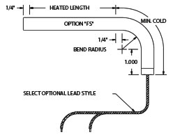
The “FS” formed sheath construciton option provides a one piece 90 degree exit formed in a cold zone of the cartridge. The formed sehath construciton is useful in liquid heating applications where the heater must make a 90 degree bend inside an enclosure and a fully sealed one piece sheath design is preferred. The formed end can also provide a self supported reorientation of the cartridge leads. The minimum raidus of the bend varies in relationto the cartridge idameter. Minimum allowable bend radisu for the vairou common cartridge diamters is indicated in the chart below. to order specific FS option noting any special radius , bend angle, and coldl ength requirements. Insure that your order includes the desi8red lead style.
| Cartridge Dia. | 1/4″ | 5/16″ | 3/8″ | 1/2″ | 5/8″ | 3/4″ | 1″ |
| Min. Bend Radius | 1/2 | 1/2 | 1/2 | 3/4 | 1 | 1 1/4 | N/A |
| Min. Cold Length | 2 1/4 | 2 1/4 | 2 3/8 | 2 7/8 | 3 3/8 | 3 7/8 | N/A |